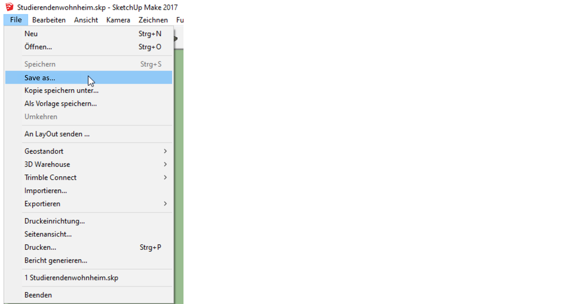
User manual
1 Installation
GenSim relies on several external software tools to deliver its functionality and conduct simulations. Below, we detail these software requirements and guide you through their installation process. It's important to pay special attention to the recommended versions of these tools. Since the development of GenSim often trails behind these other software applications, using newer versions than those recommended can lead to compatibility issues. Sticking to the suggested versions ensures smooth integration and optimal performance of GenSim in your simulations.
Download GenSim & Quickstart
The latest stable GenSim release can be downloaded from the GitHub repository here.
Quickstart:
- Download the zip-file and save it locally to your computer (don't use remote disks for better performance). Note: Strictly avoid umlaute in the file path as this can cause a crash of Excel®-VBA!
- Unpack the zip-file
- Install the required dependencies, at least Microsoft Excel® and OpenStudio® (see below for details!)
- Allow file
GenSim.xlsmto be accessed in the file property settings - Start GenSim by opening file
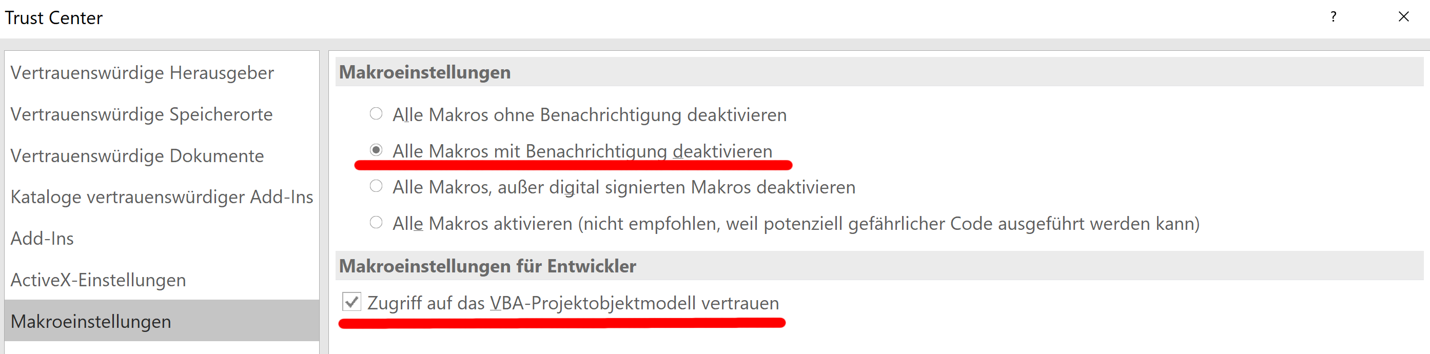
GenSim.xlsmand check the correct file paths in the INSTALLATION tab - Enable macros and access to the VBA Object Model in the Microsoft Excel® Trust Center
See chapter 2 & 3 for detailed description on how to use GenSim.
Microsoft Excel® (and possible alternatives)
The graphical user interface (GUI) of GenSim is based on Microsoft Excel®, which is required for easy access to the functionalities of GenSim. GenSim can also be used without the provided GUI via the CLI, which is described in this section.
GenSim has been tested with the following versions of Microsoft Excel®:
- Office 2016 (16.0.5422.1000)
- Office 365 (as of March 1st 2026)
Note: Microsoft Excel® may require you to enable macros before you can use the software and to enable access to the VBA Object Model. This can be done in the Trust Center in the options of Microsoft Excel® as shown in the following figure. The shown settings allow access to the VBA Object Model and allow macros to be run after prompting the user.
There is also the option to always allow macros to be run, however please note that these settings may increase the risk of malware if left on "allow all" permanently. If you regularly open Microsoft Excel® files from untrusted sources, allowing all macros to be run may lead to malware infecting your computer. To prevent this, please be mindful about when to enable and disable the use of macros.
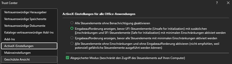
In addition, you might need to activate ActiveX elements, which is used by some input elements of the GUI. As with the settings for macros, be sure to not activate the elements unconditionally, as this might be dangerous.
SketchUp (optional)
SketchUp is a software for modelling buildings (among other things) and can be used to design a custom building model instead of using the generic approach (compare chapter 2.2). You can skip this step if you do not wish to use custom models in GenSim, however it may necessitate reinstalling OpenStudio® later if you then wish to use the functionality after all. Make sure to install SketchUp before installing OpenStudio® such that the OpenStudio®-SketchUp-plugin will be installed automatically.
We recommend using SketchUp 2017, however this version is no longer publicly available. We still need to test the use of newer versions of SketchUp for the use with GenSim. Until then it may not be possible to acquire a version that works with GenSim. Sorry!
OpenStudio®
As GenSim is based on OpenStudio®, it must be installed in order to run simulations. The currently required version is 3.10.0, which you can find on the official GitHub page for releases of OpenStudio®. The installer should guide you through the installation of OpenStudio®. Please take note of the following while doing so:
- The default installation folder should be
C:\openstudio-3.10.0. You can use a different folder, in which case you should note the installation path to specify it later in theGenSim.xlsmGUI. We recommend a folder on the same disk as GenSim. - On the installer page where you can select which components of OpenStudio® to install, please select all components.
Configuring GenSim
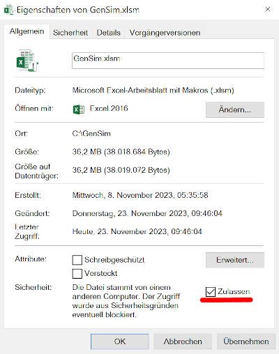
After the previous steps have been performed, you need to mark the file GenSim.xlsm to be allowed to be run and modified. Open the file property settings by right-clicking the file in a file explorer and select settings. In the settings there is an option to allow access to the file as shown in the following figure. The setting is only shown if the operating system recognises the file as an external file. If it is not there, you can skip this step.
As the last step before using GenSim, you should make sure GenSim has correctly identified the installation path of itself and that of OpenStudio®. Open the GenSim user interface (by opening file GenSim.xlsm) and navigate to the first tab INSTALLATION. Here you can configure where OpenStudio® has been installed, as shown in the following figure:
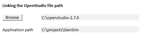
Make sure it matches the installation folder of OpenStudio® and change it if not. The Application path field is designed to automatically detect and display the directory where the GenSim.xlsm file is located. This path should be set automatically when you open the file. If for any reason the path isn't set automatically, you need to manually enter the folder path.
2 Model functions and parameters
2.1 Location
The modelling process starts on the HOMEPAGE of the GenSim Excel® GUI with the selection of the building location and the weather file.
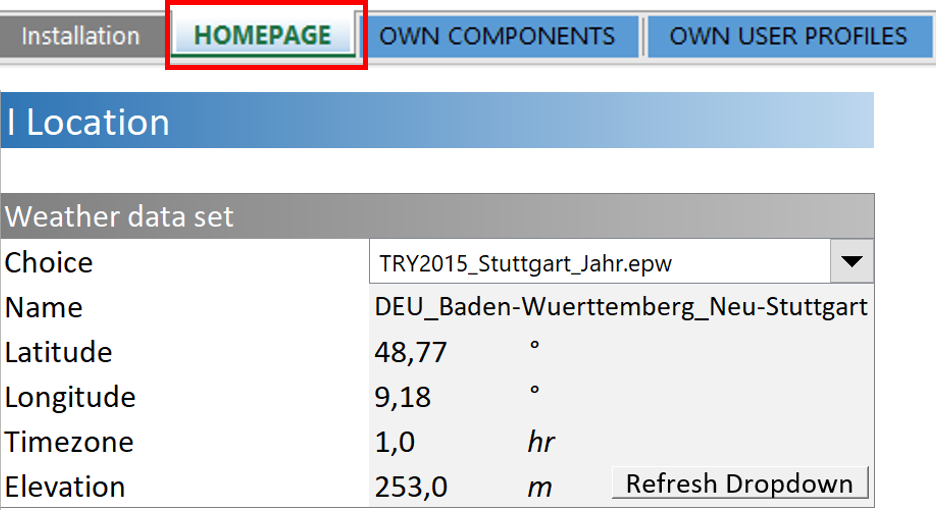
Corresponding EnergyPlus™ weather datasets1 have been generated for the 25 largest German cities using the current DWD test reference years (TRY 2015/2045). Both the current TRY20152 and the future scenario TRY20453 have been stored in order to be able to consider the climatic requirements for heating, air conditioning and ventilation systems over a longer period of operation. The required weather data set can be selected from a dropdown list.
Custom weather data sets
In general, any EnergyPlus™ weather data set can be used in GenSim as long as it is in the EPW file format. Often a DDY file is created alongside the EPW file. As of v2.16, this file is no longer required and the necessary data is automatically calculated. It can optionally still be used, but this requires the use of the GenSim CLI, which is not covered by this manual. The EPW file (+DDY) must be saved subfolder "Wetter" in the GenSim base directory. The refresh button can be used to update the selection of weather files in the dropdown list within the GUI.
Ready-to-use weather data sets (EPW + DDY) for worldwide locations can be downloaded free of charge from the following websites:
https://energyplus.net/weather
http://climate.onebuilding.org/
Furthermore, the TRY data provided by the DWD can be used to generate location-specific weather data sets for the whole of Germany which can then be converted into valid EPW files using the EnergyPlus™ Weather Converter.
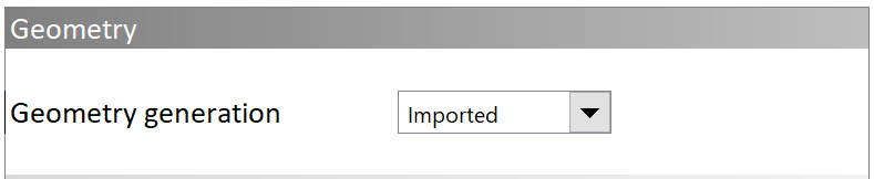
2.2 Building geometry
The building geometry can be defined in two ways. Either a generic cubic geometry model can be parameterised directly in the GUI of GenSim, or the geometry can be individually created using SketchUp and imported to GenSim. The choice between these two options is made using a drop down menu (see the following figure). Both options are described below.
Basically, in EnergyPlus™, the geometrical model of a building is represented by its external dimensions without any component thicknesses or volumes (e.g. wall or ceiling thicknesses). As a result, the entire gross floor area (GFA) or gross room volume (GRV) is simulated as the volume to be conditioned. The inaccuracy resulting from this simplification is negligible given the low level of model detail. The user-defined net floor area (NFA) (or rather the ratio GFA/NFA, see below) is later used to convert the simulation results to area-specific quantities related to the NFA. This means that the absolute results of the simulation are related to a typical NFA corresponding to the simulated GFA.
2.2.1 Generic building model
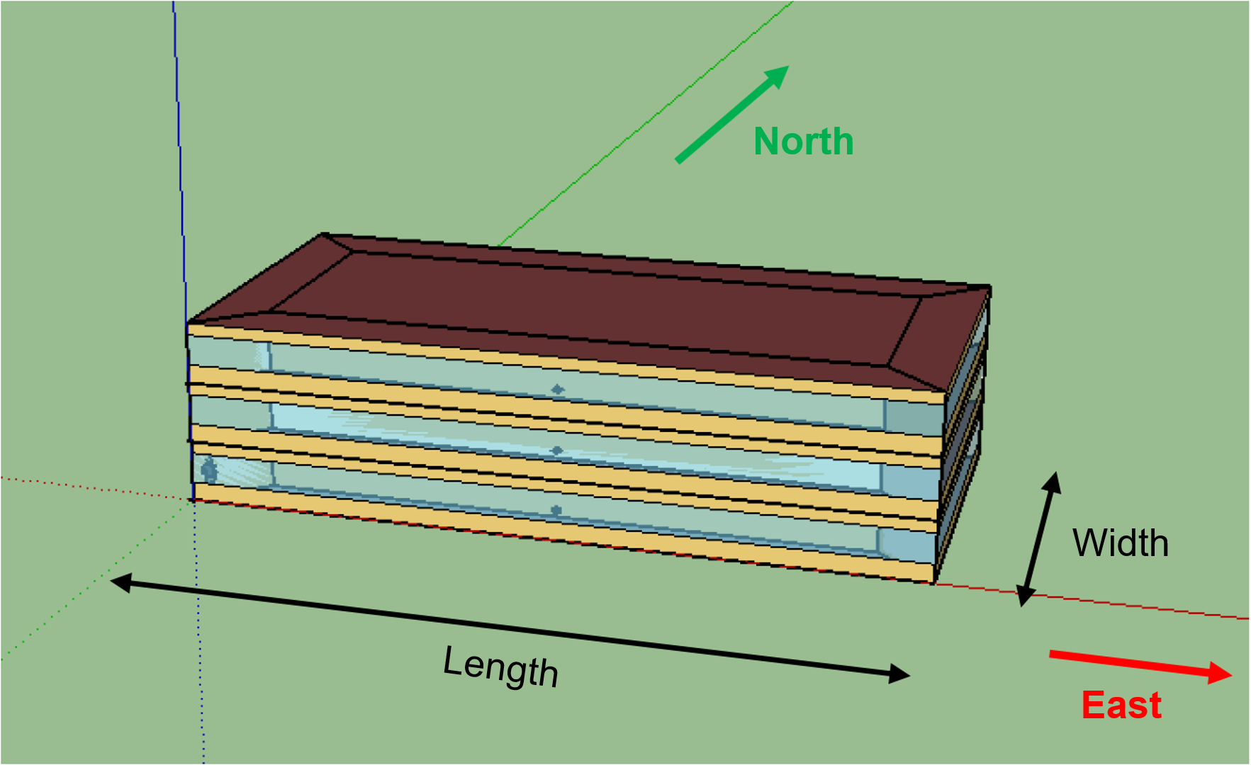
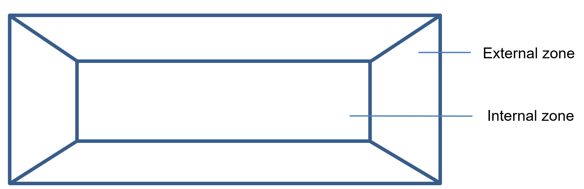
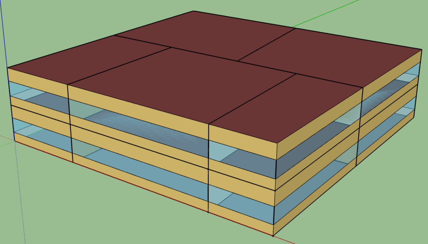
The generic geometry model is a cubic building (see figure) defined by the parameters "length", "width", " floor height", "number of floors" and "window area percentage"4 (see figure). An idealised floor plan is used which divides each floor into 4 external and one internal zone (see figure below).
After the simulation, it is possible to view the generic geometry model in SketchUp® using the OpenStudio® SketchUp plug-ins. The geometrical model file is located in the directory "/Output/run" under the name "in.osm".
Measurements
The "length" and "width" of the building are indicated as external dimensions. The length is defined as the the north-south facing facade and the width as the east-west facing facade (see figure above). The "floor height" is specified as the gross floor height. The multiplication of "floor height" and "number of floors" results in the total height of the building. The parameter "depth outer zones" additionally defines the depth of the outer zones5 according to the figure above. All input parameters for the generic geometry model are shown in the figure below and will be described in the following.
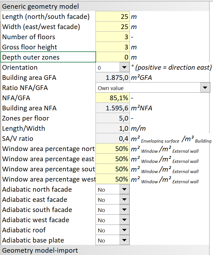
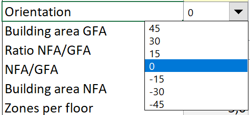
Orientation
The orientation of the building can also be changed using a drop down menu (see following figure) if the building is not orientated in the axes of the main cardinal points. A positive rotation of the building corresponds to a clockwise rotation6.
Ratio NFA/GFA
As already mentioned, only gross areas or volumes are represented in the EnergyPlus™ model. In order to convert the absolute results of the simulation into area specific results with the unit , the user needs to specify the ratio of GFA/NFA. This can either be entered as an individual value (if known) or it can be determined from various predefined building typologies included as presets in the GUI.
Window areas
Besides the actual geometry, window areas of the building also need to be defined. Therefore, a corresponding "window band"7 is modelled by specifying a percentage of window area per facade (m² of window area / m² of facade area [%] - see following figure).
Adiabatic external components
Optionally, individual facade components or the roof and floor plate of the building can be defined as adiabatic. Adiabatic means that the component does not allow heat transfer. This allows the simulation of e.g. coupled terraced houses or other sub-volumes of a whole building by defining component boundaries facing to heated zones as adiabatic. The procedure for the imported geometry model is explained in more detail below in chapter 5 in the section on adiabatic external components.
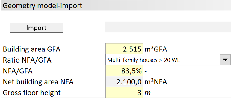
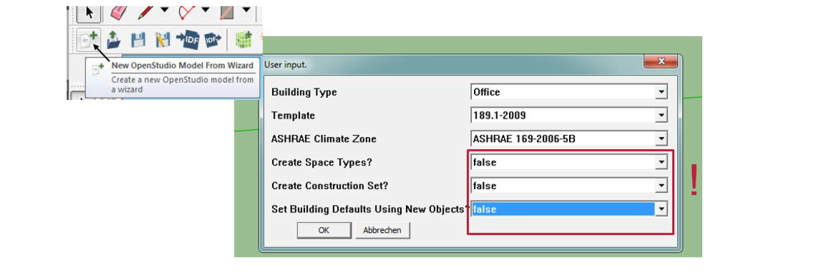
2.2.2 Imported geometry model
As mentioned above, an individual geometrical model can optionally be created with the OpenStudio® SketchUp® plugin if the building geometry is known in more detail and/or significantly differs from a cubic shape. The osm-model file created this way can be imported into GenSim by the Import button (see following figure). A short tutorial on how to create your own geometry model can be found in chapter 5. Currently, the GFA of the imported OpenStudio® model is not read in automatically by GenSim, so the user must enter it manually. It can be determined by perfomring a test-run of GenSim. The actual GFA of the imported model ("Total Building Area") can then be found in the file "eplustbl.htm" in the "/Output/run" folder and entered into the GUI for the actual simulation. The (gross) floor height of the imported geometry model must also be entered.
2.3 Building usage
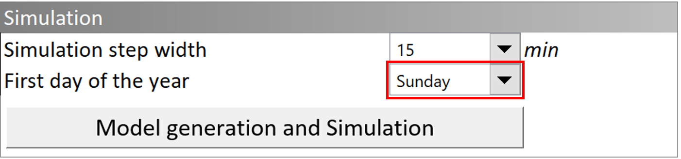
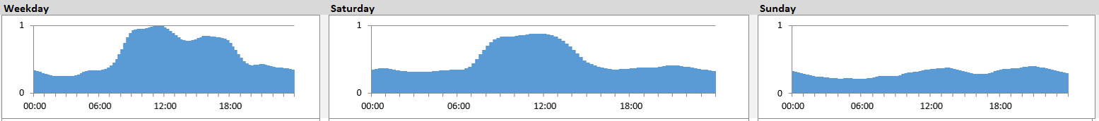
By using electrical devices, users of a building directly influence the electricity demand of a building. In addition, the usage of the building also has a significant impact on the heating and cooling demand in the form of internal heat loads from electrical devices and lighting as well as heat emitted by the present people and their activity. The internal heat loads of these three groups (electrical devices, lighting, presence of people) are defined by normalised load profiles and by power and occupancy densities for the scaling of these profiles. The load profiles are specified as individual typical days for working days, Saturdays and Sundays (see following figure). In addition, it is possible to define individual time periods for public holidays/vacation and corresponding load profiles of typical days for these time periods. Depending on the parameter "first day of the year", annual load profiles are generated on the basis of the individual normalised typical day profiles, the scaling factors and the arrangement of working days, weekends and user-defined holidays within the year. In the GUI, presents for the typical days are specified and can be accessed by dropdowns (more details below).
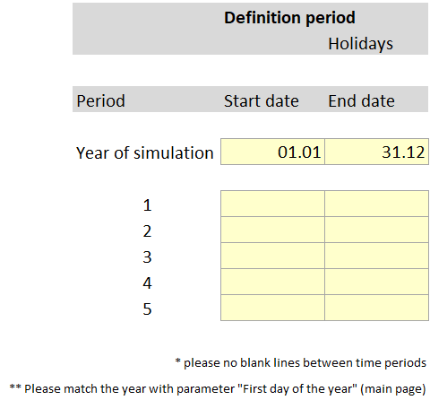
Up to 5 periods can be defined for public holidays/vacation days (see following figure). These can be holiday periods e.g. for the simulation of a school or university building.
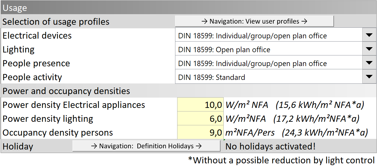
Electrical devices and lighting
The typical days for electrical devices and lighting are available in the form of normalised profiles. The range of values is therefore between 0 ... 1. Multiplying the corresponding power density in with the normalised dimensionless typical day profile results in a profile in . See the following figure: "Electrical devices" and "Lighting" drop-down menus as well as the "Electrical device power density" and "Lighting power density" parameters.
Person occupancy and activity
Two separate typical day profiles are defined to represent the occupancy of persons and their activity: A normalised profile describing the presence of persons (0...1) and additionally a profile describing the activity of the present persons with the unit power per person (). By multiplying these two profiles with the person occupancy (defined in ), the result is - like for electrical devices and lighting - a profile in ( * ).
Default values for these four categories are available, which were created using the characteristic values described in various sources:
- SLP BDEW: Standard load profiles from the German Association for Energy and Water Management
- DOE Prototype Buildings: Commercial Prototype Building Models from the US Department of Energy
- DIN V 18599-10: DIN standard Energy performance of buildings part 10
- VDI 2078: 1996-07: VDI standard Assessment of cooling load of air-conditioned rooms
It is also possible to define all profiles yourself. Custom profiles can be entered in the tab OWN USER PROFILES of the GUI and then selected in the respective drop-down menu:

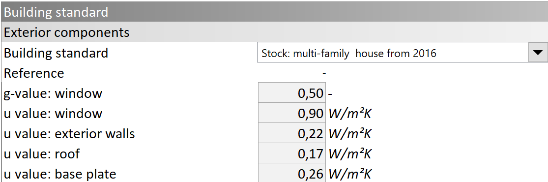
2.4 Building standard
2.4.1 External components
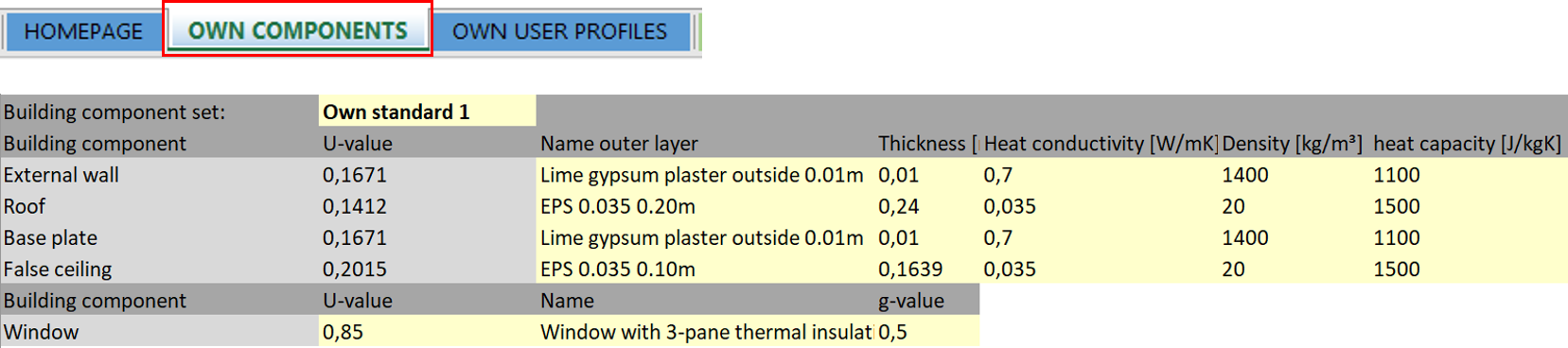
A number of pre-defined component structures for the external components of the building (walls, roof, base plate, ceiling, windows) are included in the GUI. These can be selected from the drop-down menu, as shown in the figure below. Additionally, it is also possible to define own component structures, using the menu OWN COMPONENTS shown below. Here, all the required physical values for the external walls, roof, floor plate, intermediate ceiling and window component groups can be entered for custom structures. Note: The heat transmission coefficient of opaque components is calculated from the layer thicknesses and specific thermal conductivities of the materials and the heat transfer resistances. When creating new layers, all physical properties must be fully described.
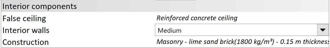
2.4.2 Internal components
Internal components, defined as false ceilings (see last subchapter) and internal walls, affects the simulation results significantly as they act as internal storage masses for thermal energy. The building standard of the internal walls can be selected by a drop-down list as "light", "medium" or "heavy". The GUI provides corresponding typical structures, shown when changing the value in the drop-down menu.
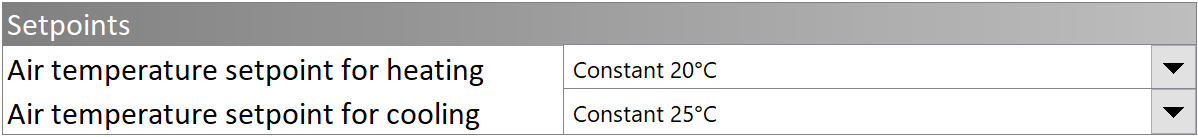
2.5 Air temperature setpoint
The air temperature setpoint for heating and cooling are set in the same way as the usage profiles (see chapter 2.3) by two drop-down menus (see figure below). They can be taken either from predefined standard profiles or from user-defined custom ones.
2.6 Ventilation system
To represent the ventilation system, the system type and the heat recovery (HR) option must be selected in two drop-down menus (see figure below). If the HR is activated, a return heat or return humidity value must also be specified. The operating times of the ventilation system are defined in the same way as the usage profiles (see chapter 2.3) using a drop-down list either from predefined profiles or by selecting a user-defined profile. The actual air flow rate of the ventilation system is determined by specifying the "air change rate" parameter and a "conditioned room height".
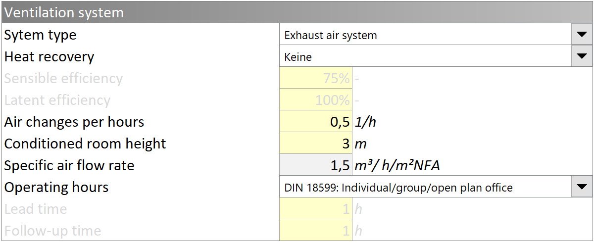
The electrical power demand of the ventilation system and therefore the resulting heat input into the ventilation system considered in the simulation is based on the standard SFP (specific fan power) factors of DIN EN 16798-3. The specific fan power is set to 750 for supply and extract air corresponding to SFP 2.
2.7 Furthermore
There are a number of optional model features that can be activated which are explained below.
Window ventilation in case of overheating (cooling)
In order to simplify window ventilation (for cooling) in case of overheating of the rooms, the function "window ventilation in case of overheating" can be activated (see following figure). This requires the specification of "air changes per hour" (typically 1...2/h) and a threshold for the room temperature at which occupants may open the windows. Actual window ventilation of the overheated rooms will only occur if, as a further condition, the temperature difference between the indoor air and the outdoor air meets a minimum value. If a value of 1 Kelvin is set for this parameter, then the temperature of the outdoor air must be at least 1 K below the temperature of the indoor air for the window ventilation to actually become active during the simulation. This parameter can be set to 0 Kelvin as the default setting.
Infiltration
By defining the air changes per hour (see following figure) a constant air exchange rate is applied to all conditioned zones of the building during the simulation to reproduce the building's leakage. Reference values can be found in the GenSim reference library.
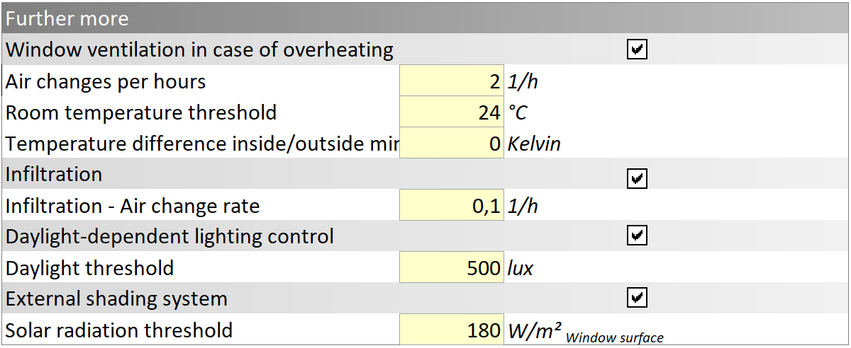
Daylight-dependent lighting control
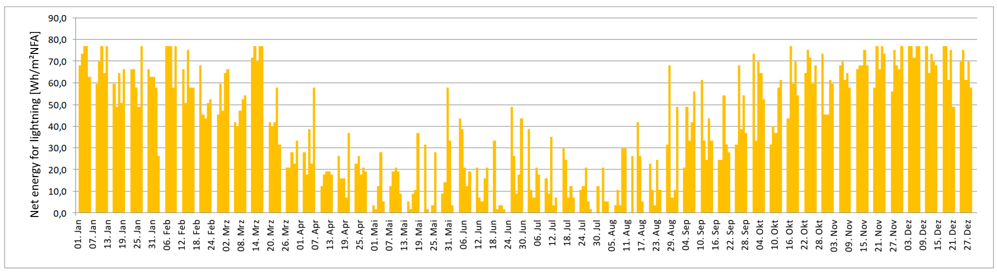
Daylight-dependent lighting control can be activated to realistically simulate user behaviour in terms of artificial lighting operation depending on the daylight available in individual rooms. When a certain level of daylight is reached (see parameter "daylight threshold" in the figure above) the lighting in individual rooms is deactivated, overwriting the state set by the "lighting usage profile". This leads to the typical seasonal character of the lighting profile as shown in the following figure:
3 Simulation
Once all the parameters have been entered, the simulation is started using the "Model generation and Simulation" button (see following figure). During the following completely automatised process, the EnergyPlus™ model is generated in the first step. This turns the generic model into a customised EnergyPlus™ building model. In the second step, the generated building model is simulated with the specified time step width (according to the parameter in the following figure).
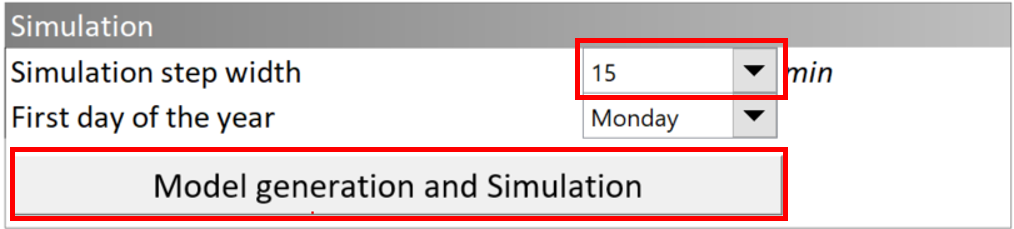
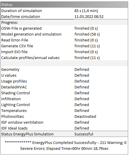
The user is continuously informed about the progress of the model generation and simulation, as exemplary shown in the figure below. At the end of the simulation process, the results of the EnergyPlus™ simulation are imported into the Excel® user interface.
4 Results
The results of the simulation are given as annual values and profiles. Annual values can be found on the HOMEPAGE and under the menu item BUILDING BALANCE. The main profiles are displayed under ENERGY DEMAND. More profiles can be found at e+ Outputs. A graphical representation of the main profiles can be found under the menu item PROFILES VIEW. The output of the results is assumed to be intuitive so no further explanation is provided here.
5 Tutorial: Using the GenSim CLI to run a simulation
GenSim also has a CLI written in Ruby, which is especially useful to run simulation without using the GUI. However, in this case the required input OSW-file needs to be created in some other manner. The GenSim CLI uses the same OpenStudio® CLI calls as the GUI does, therefore with the same inputs it should produce the same results as the workflow using the GUI.
While OpenStudio® also uses Ruby and ships with internal binaries, these cannot be used outside of OpenStudio®. You will need to have Ruby installed separately and the CLI has been tested with version 3.4.7. In the following it is assumed that ruby and gem point to a working installation of Ruby and the package manager. To use the CLI to you need to (once) install its dependencies with: gem install thor
In the following are the steps of how to run a simulation, assuming you have a valid OSW input file called Model.osw:
- Switch to the GenSim directory:
cd /path/to/GenSim- In the following it is assumed that the shortcut
.stands for this path. Although using relative paths using.should work, this cannot be guarranteed on all platforms. If the commands are not working, try using absolute paths instead.
- In the following it is assumed that the shortcut
- Create an empty OSM-file:
ruby ./Measures/gensim_cli.rb create_empty_osm --output_folder=./Output Model.osm - Run the simulation:
ruby ./Measures/gensim_cli.rb run_workflow --output_folder=./Output --os_bin_path=C:\openstudio-3.10.0\bin\openstudio.exe Model.osw - The results are saved as CSV files in
./Output/reports. They are available as absolute values, relative to the NFA, relative to the GBA and as yearly sums. You typically only need to use one of these files, as they are all derived from the absolute values and saved in different files for convenience.
6 Tutorial: Creating a geometry model with the OpenStudio® Sketchup®-plug-in
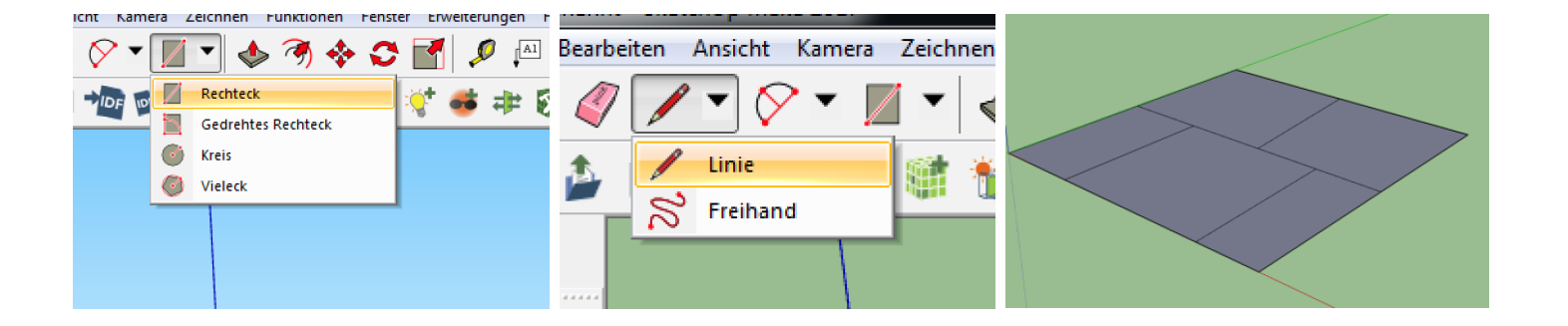
Create a new empty model
In order to correctly create a custom, non-generic geometry model for a thermal building simlation in GenSim, the model has to be created from scratch without any predefinitions, as shown in the following figure.
Draw a floor plan
Dimensions must be used for a correctly scaled model. This option may need to be activated in SketchUp itself as it is not always activated by default during installation in order for the dimensions to be displayed in the lower section. To do so, click on "View" in the menu bar and then on "Toolbars" in the pull-down menu. In the "Toolbars" tab the "Dimensions" option must be activated. The dimensions will then appear in the bottom left corner of the program and can be easily entered (without clicking on the field). The entry of a dimension is completed and confirmed by pressing the Enter key.
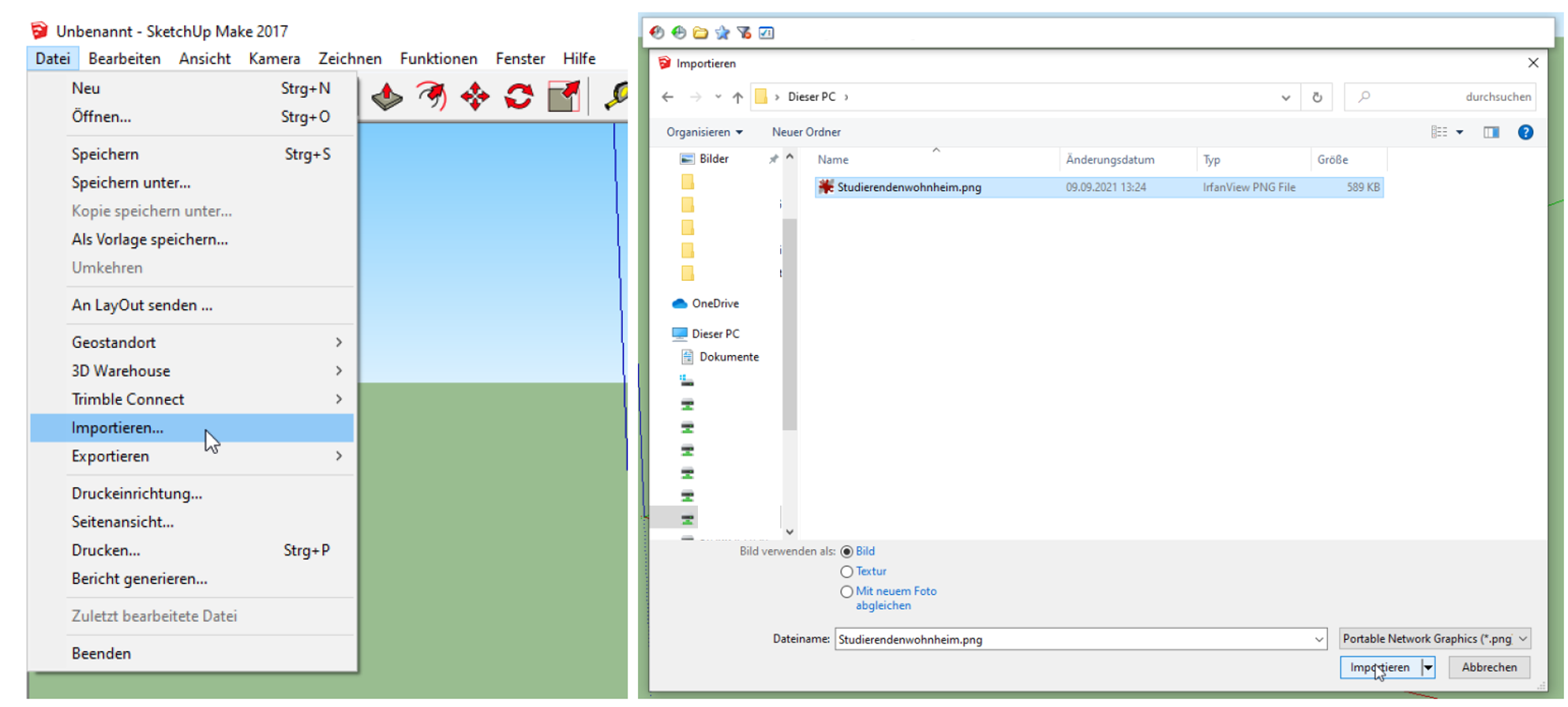
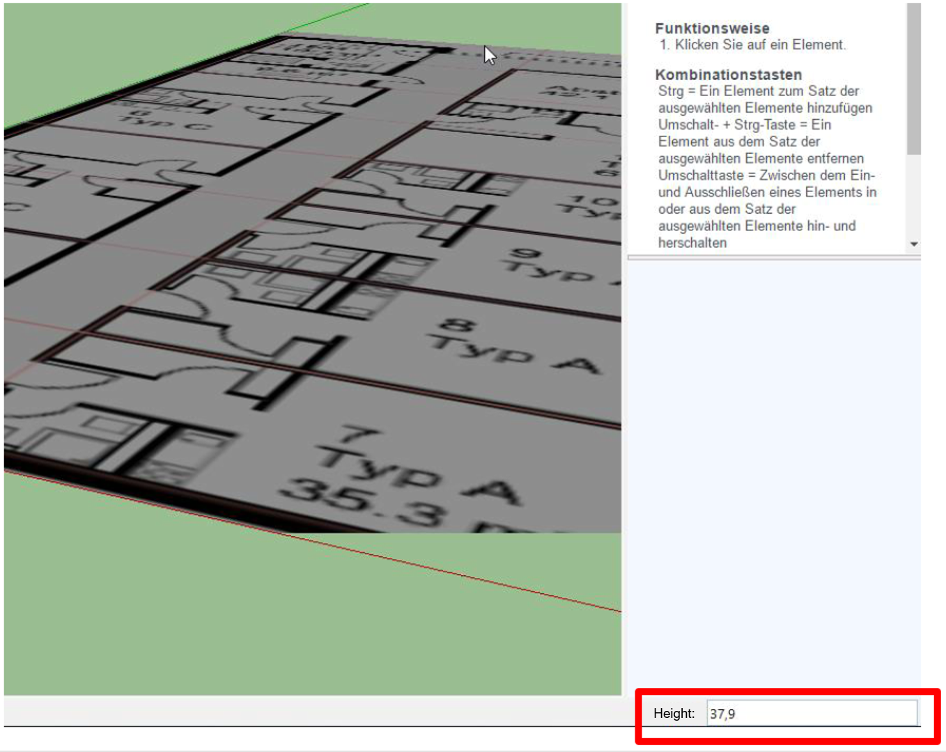
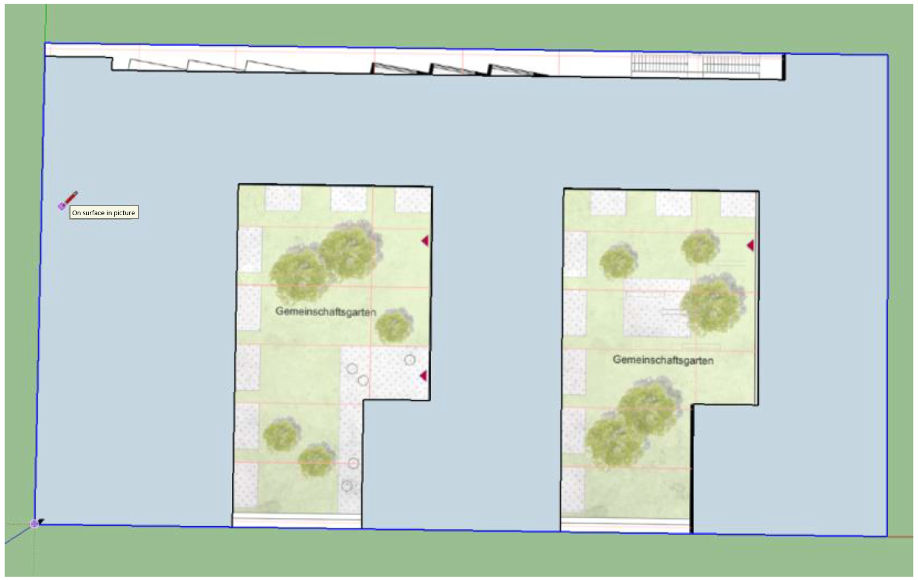
It is important to not only draw the outline of the building but also the individual rooms in the floor plan so that the effects of different heating and cooling loads in individual rooms (depending on the solar input, etc.) are adequately represented. It is recommended to import the floor plan (if available) into SketchUp as an image file to make it easier to trace the individual rooms. Therefore it is necessary to know a length in the image. Preferably the length of the entire exterior wall of the building so that you can scale the image in SketchUp. Scaling works as described above.
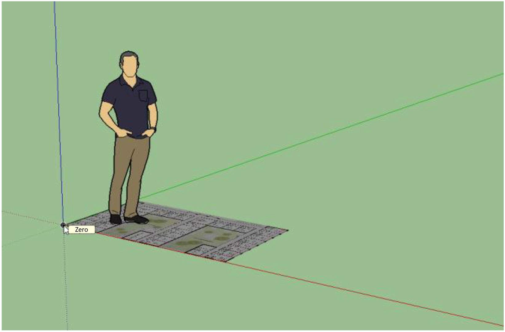
Set zero:
Scale by entering the length of the image:
Trace the building outline:
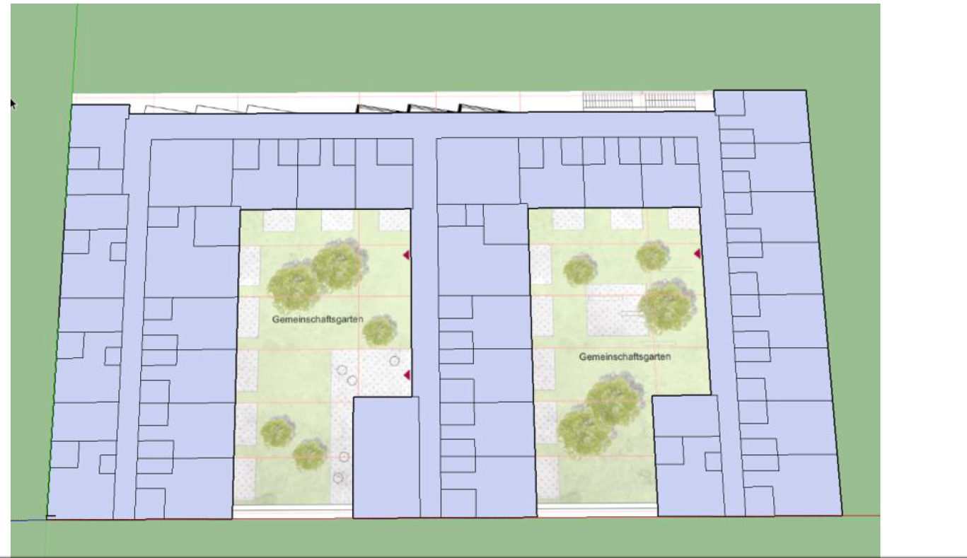
Switch on X-Ray mode:

Trace individual rooms:
After drawing the floor plan of the building, it is recommended to first save the file temporarily as a SketchUp file (.skp file type) so that it can be accessed later and corrected if necessary.8
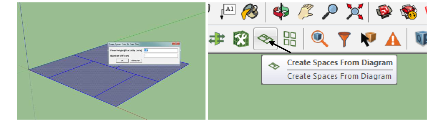
Select floor plan and create floors
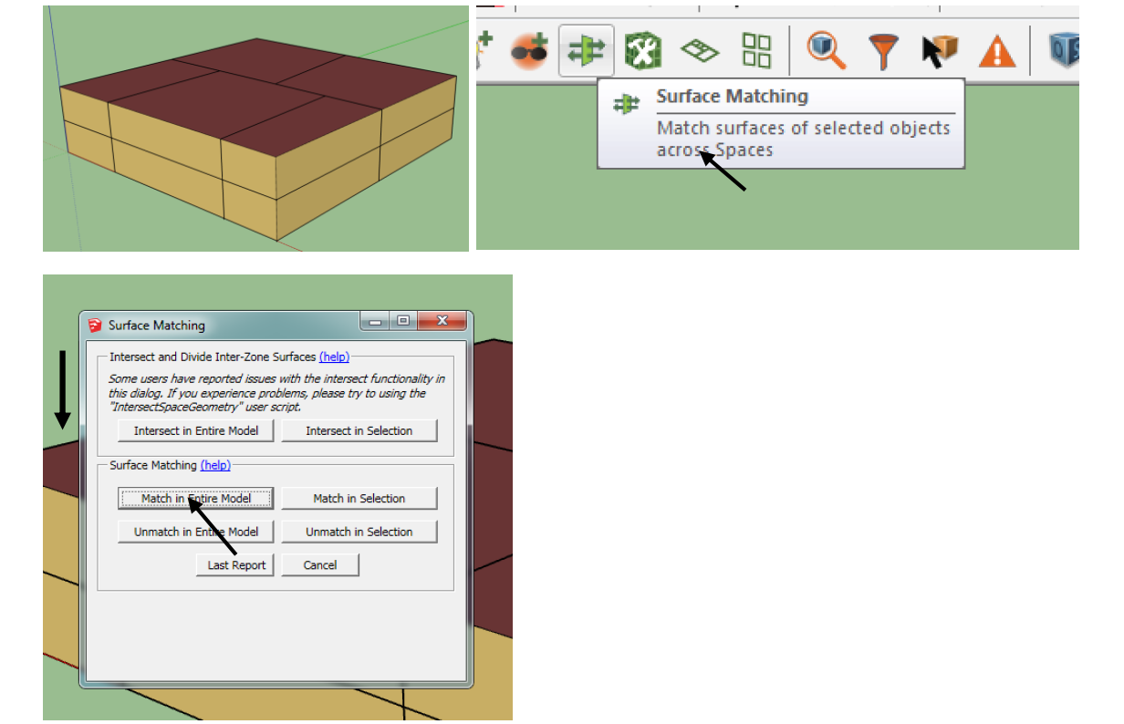
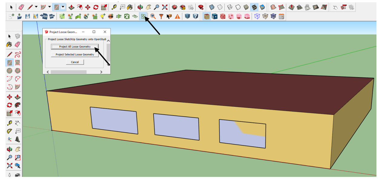
Surface Matching
Once the final steps have been completed the file can be saved as an OpenStudio® file (.osm). This file is then linked in GenSim (Excel® interface) - see chapter 2.2.2.

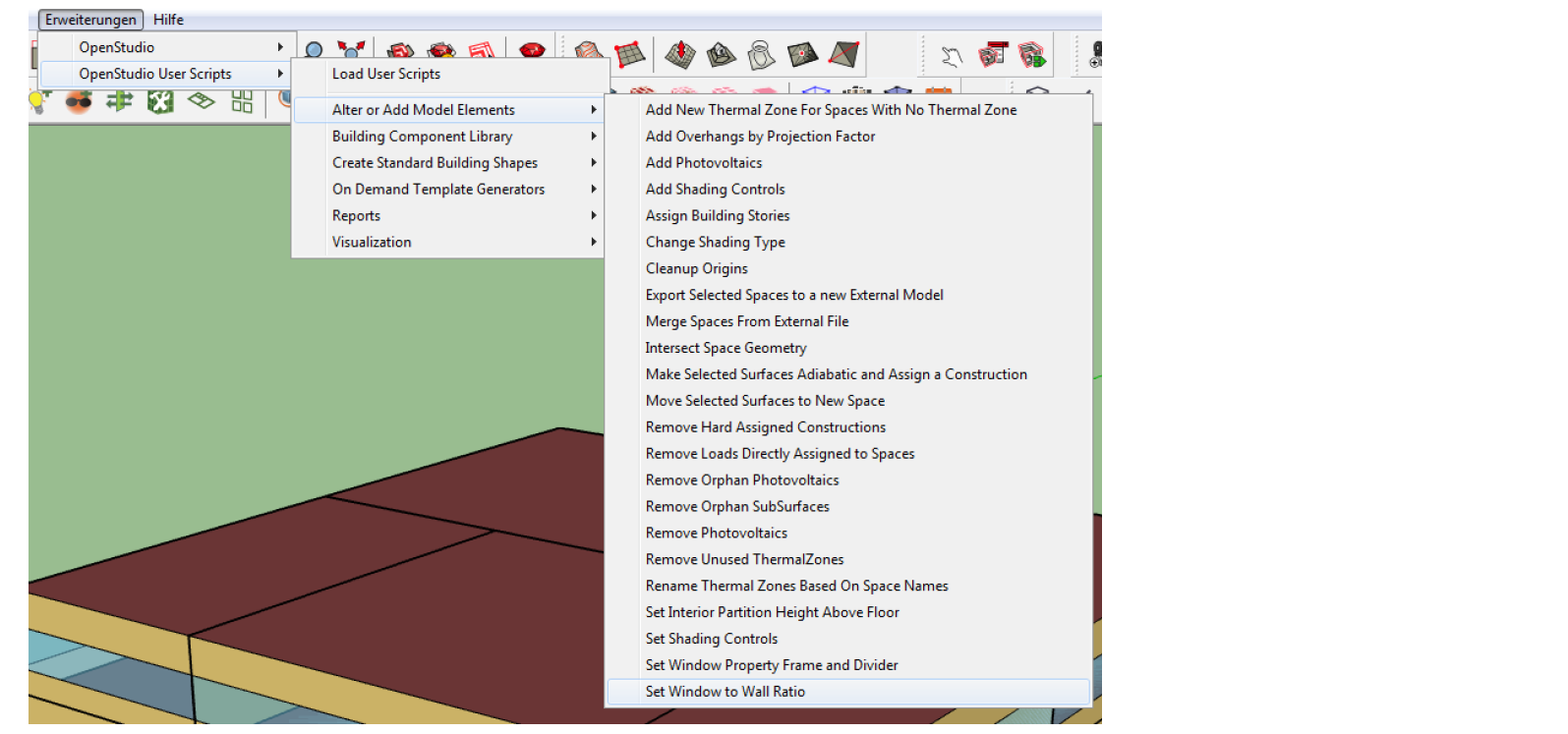
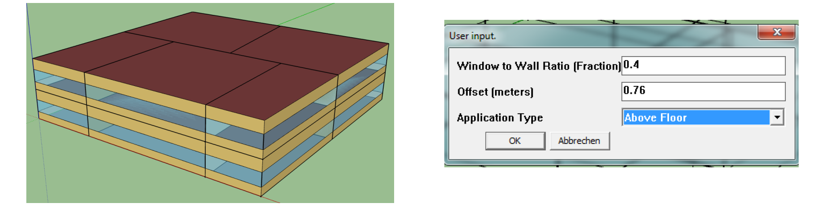
Create window bands
Select the model or rooms of interest. If not all rooms have a constant proportion of window area but should have different sizes according to different external facades, the individual facade elements can be selected by double-clicking. Once the rooms or facades have been marked, the window bands are inserted as shown in the following figure. The "window to wall ratio" is the ratio of window area to facade area.
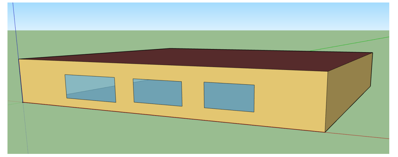
Save final model as an OpenStudio® model (.osm)

Useful Links
Roof geometry: https://www.youtube.com/watch?v=7YRnquHx1AE
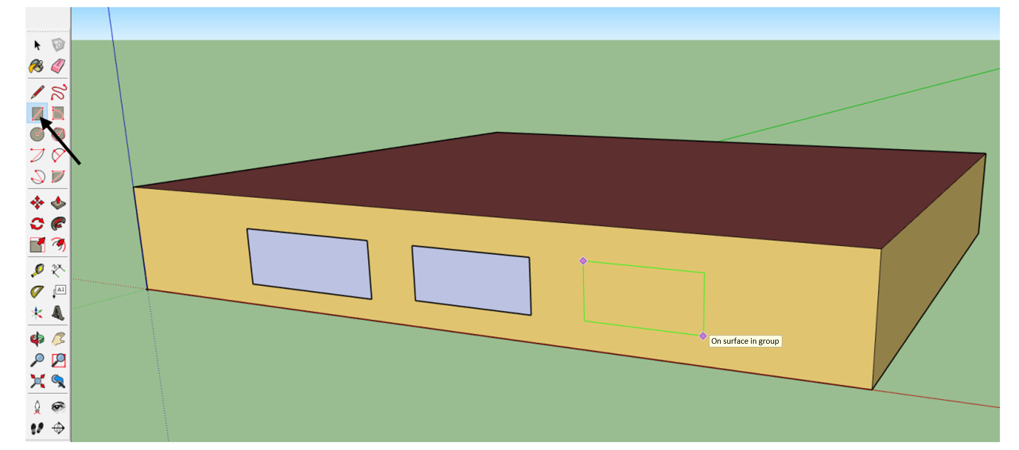
Optional: Draw windows by hand
Optional: Adiabatic external components
Optionally, individual facade components as well as the roof and floor plate of the building can be defined as adiabatic. Adiabatic means that the external component does not allow heat conduction. This can be used e.g. to simulate coupled row houses or any other partial volume of a whole building by defining component boundaries to heated zones (simplified) as adiabatic.
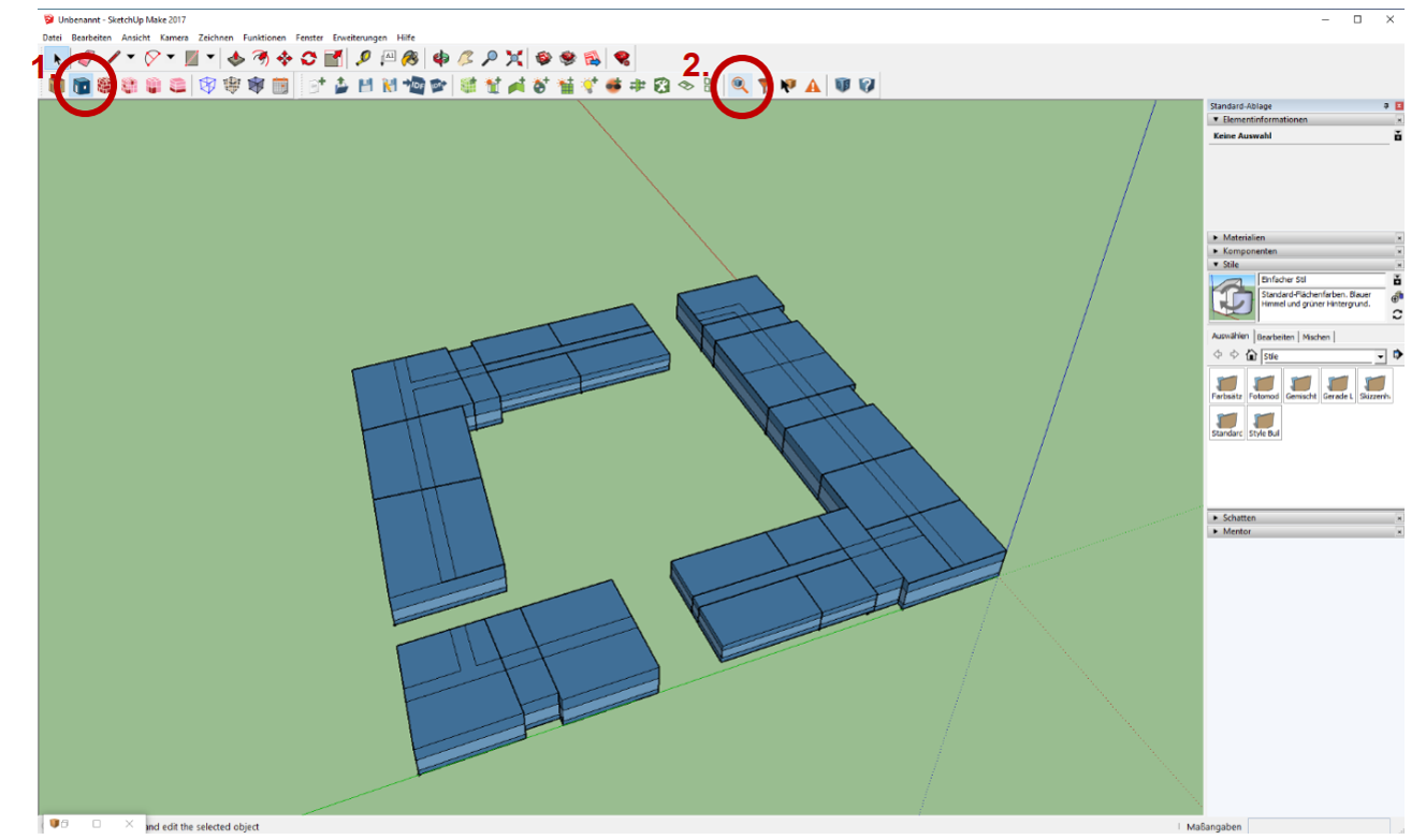
- Change the display to "Render By Boundary Conditions"
- If it is not displayed: Extension > Open Studio > Rendering > Render By Boundary
- Open the "Inspector" and change the item "Outside Boundary Condition" to "Adiabatic"
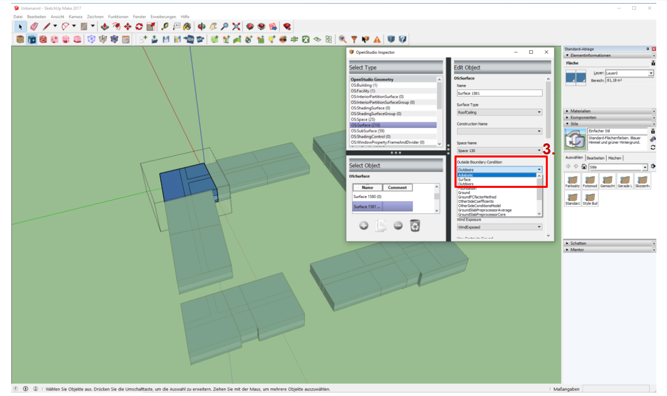
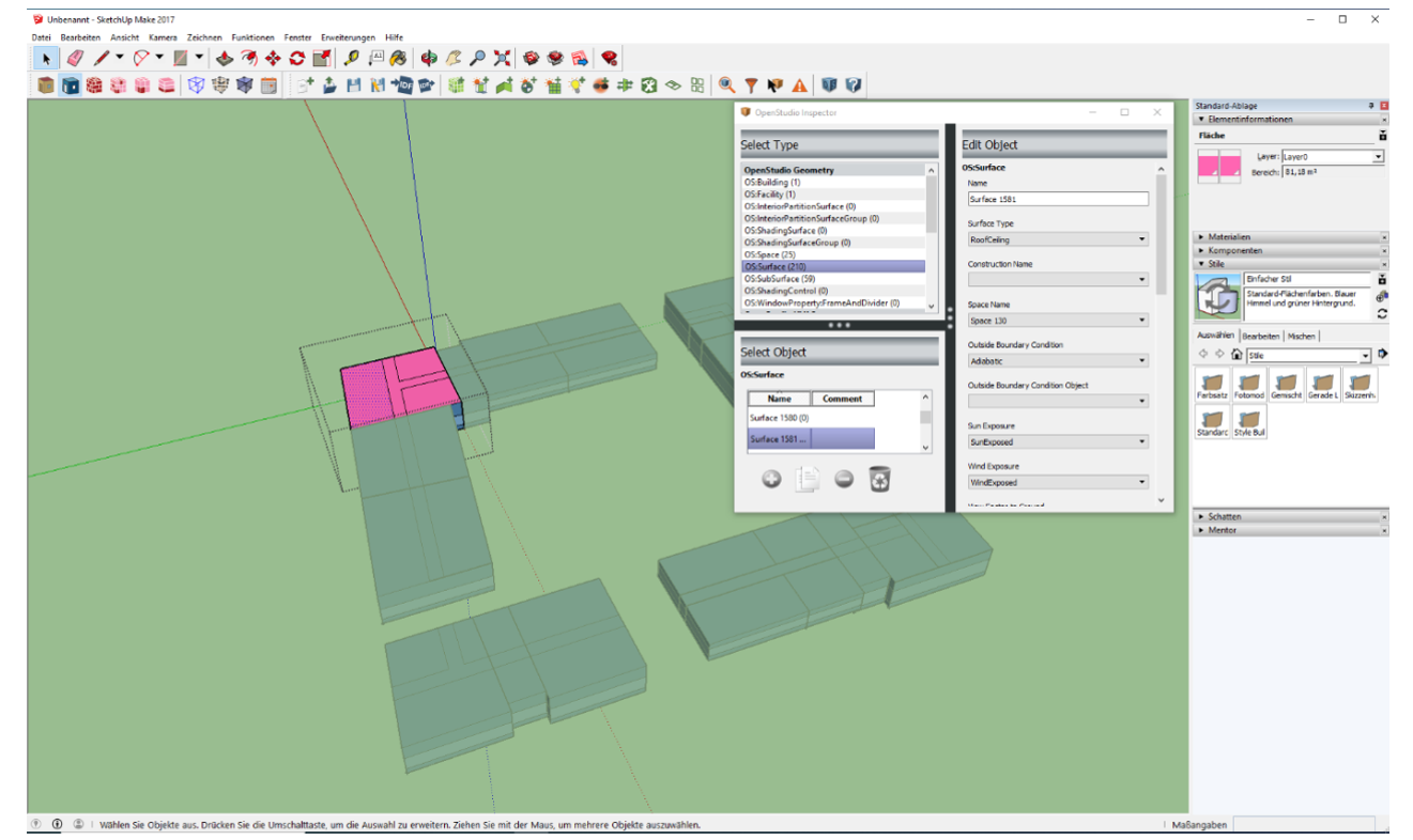
- If the floor (e.g.) is to be set as adiabatic, the floor must be selected by double clicking on it. If this does not work, double click again.
- The colour of the previously selected area should now change to pink. Tip: If the colour does not change, it usually helps to restart the program and open the .osm file again. This is simply a display error in the plugin. The colours of the areas will change to the correct colours after the restart.
-
File format "epw" - EnergyPlus™ weather data ↩
-
Reference period 1995 to 2012 ↩
-
Forecast period 2031 to 2060 ↩
-
Ratio of transparent to opaque outer surface ↩
-
An outer zone with a depth of 0m results in a one-zone model ↩
-
See EnergyPlus™ parameter "north axis": https://bigladdersoftware.com ↩
-
Ratio of transparent to opaque outer surface (window without frame) ↩
-
This is because once a building model is created from the floor plan it disappears in SketchUp. ↩