Operation and control
An important part of what makes ReSiE's simulation model different from similar tools is how the control of energy system components is handled. Actualized energy systems, as they are built in real buildings, have a complex control scheme that also incorporates aspects that are not part of the model, such as hydraulic components. This in turn requires that these complex control schemes can be modeled as close to reality as possible while staying inside the fundamental model of energy balances.
Control behavior
The calculations for control have been decoupled from those of energy processing, so that processing can work as a function depending on the result of the control. In the simplest case, control turns components on and off, but the implementation of various components might take many more cases into account. The latter already is arbitrarily complex1, so the former must be as well.
To facilitate this, all component implementations have access to a controller, that has access to information defined by its operational strategy and provides state information to the processing functionality.
State machines
State machines are a common concept in computer science and are useful in working with state based on predefined conditions. They have also been used in programming the building control system of actualized building. In the simulation model they are used with some modifications as described in the following.

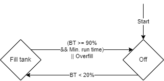
The example above shows a state machine with two states "Off" and "Fill tank" that starts in state "Off". Between the two states are transitions based on boolean expressions of complex conditions. When the state machine is checked to advance its state2 and the expression of a transition evaluates as true, it is followed to the new state.
One addition to the common concept of a state machine is that the implementation in ReSiE keeps track of how many steps a state machine was in the current state.
Conditions
The conditions used in evaluating the boolean expressions of transitions are arbitrarily complex and as such depend on the implementation. However the code handling them must define which information it requires for evaluation. In particular a condition must define to which components it needs access. As the specific components are not defined before the project is loaded, these requirements affect the type and possibly the medium of the components, e.g. a condition might ask for "a grid connection of medium m_e_ac_230v" or "a PV plant". It can also provide customizable parameters with default values.
The example above uses three different conditions:
BT >= X%: Checks if a linked buffer tank is above X% capacity.BT < X%: Checks if a linked buffer tank is below X% capacity.Min. run time: Checks if the component the state machine controls has been in the current state for longer or equal than its minimum run time.
To make sure that the buffer tank is not overfilled, the component linked to this buffer checks this condition itself during each timestep by comparing the free storage space and the possible energy that could be delivered to the buffer tank while considering the minimum partial load of the component. Therefore, this condition is not included in the state machine.
Truth table
The transitions for each state are defined using a truth table over the conditions involved, resulting in a new state (which may result in the current state again). This has the advantage that is covers every possible case implicitly, but also has the disadvantage that this might result in large truth tables for state machines with many conditions.
| BT >= X% | Min. run time | New state |
|---|---|---|
| true | true | Off |
| false | true | Fill tank |
| true | false | Fill tank |
| false | false | Fill tank |
The example above shows the truth table used for the state "Fill tank", which has two conditions. In this case, the buffer tank should be filled exept of the case where both the minimum run time has reached and the buffer tanks is filled above the defined upper load state. The condition to not overfill the buffer tank is handled by each component during each time step and not by the state machine.
Strategies
Instead of requiring the user to manually specify a state machine, it is desired to provide a number of predefined operational strategies that can be selected. Apart from simplifying the user input, this also makes it easier to enable processing behavior that depends on the chosen strategy, but not necessarily the current state of the controller as it may not need a state machine for control calculations.
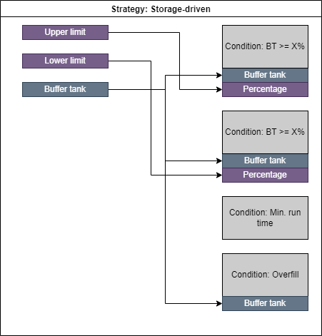
For the given example above this would be best described as a storage-driven strategy as a component with this strategy would try to fill the linked storage component when it gets too low. The required linked components and parameter values are carried over from the state machine constructed by the strategy to the required user input as illustrated in the following:

This leads to the required user input in the project file:
"TST_01_HZG_01_CHP": {
    "type": "CHPP",
    "control_refs": ["TST_01_HZG_01_BFT"],
    "output_refs": [
        "TST_01_HZG_01_BUS",
        "TST_01_ELT_01_BUS"
    ],
    "strategy": {
        "name": "storage_driven",
        "high_threshold": 0.9,
        "low_threshold": 0.2
    },
    "power": 12500
},
A CHPP is operated by this storage-driven strategy, which requires two parameters high_threshold and low_threshold as well as a linked buffer tank, which is added in the control_refs of the CHPP. The user does not need to know about the implementation of this strategy, only about the meaning of its parameters.
Another use of operational strategies is controlling the processing code without the use of a state machine. For example a demand-driven strategy requires only that any component is linked, with no specification as to which. This in turn is done so that determining the order of execution of simulation steps places the linked component before the controlled component. Otherwise the controlled component might try to meet a demand that has not been calculated yet.
For the predefined demand_driven, supply_driven and storage_driven control strategies, optional parameter flags can be set in the input file. Their default value is always true if the parameter is not given in the input file.
    "strategy": {
        "name": "demand_driven",        // required
        "load_storages" : true,         // optional
        "unload_storages" : true,       // optional
        "operation_profile_path": "path/to/profile.prf",  // optional
        "consider_m_el_in" : true,      // optional
        "consider_m_el_out" : true,     // optional
        "consider_m_gas_in" : true,     // optional
        "consider_m_h2_out" : true,     // optional
        "consider_m_o2_out" : true,     // optional
        "consider_m_heat_out" : true,   // optional
        "consider_m_heat_in" : true     // optional
        },
Each entry of consider_*medium* defines an input or output of the related component. Obviously, a component has only a selection of the full list of inputs and outputs given above. If an input or output is set to false ("consider_medium": false) within the control strategy, the limitation of energy demand or supply on this interface is ignored when the current operation state of the component is determined. Note that this can lead to unexpected balance errors within the simulation! However, if users want more control over the operational strategy, these flags can be used to define complex rules for the operation of each component. As default state, all in- and outputs are considered when determining the state of a component in every time step (flags set to true).
If the other two entries, load_storages or unload_storages, are set to false, the specified component is not allowed to load or unload any storage in the energy system. While the control matrix of each bus can only handle storages connected to the specified bus, this parameter allows to deny or allow system-wide storage loading or unloading for each component. Note that these rules are intersecting with the control matrix of a bus and storage-loading has to be allowed at both the control matrix and by the flag load_storages. If one of these rules is set to false, the loading is not allowed.
Using the storage_driven control strategy, load_storages and unload_storages can also be set to false, although this is usually not very useful.
The operation_profile_path entry within the strategy-struct can be used to specify a path as a string to a *.prf file containing a timestamp and values between 0 and 1 for each time step. They serve as an additional operation limitation for the transformer and can be used e.g. to operate a transformer only at times with a high share of renewable energy in the public power grid.
-
In the sense that each component can perform any number and kind of calculations using the current state of the simulation that the component has access to. ↩
-
Usually this happens once a simulation step for each state machine, but in the general definition of a state machine this is not time-dependant and works on "turns". ↩